Camera Calibration Using Homography Estimation

photo generated by Midjourney image engine
This article explains how to map pixel distances on 2D images to the corresponding real-world distances in 3D scenes using Homography Estimation and applies this approach to a practical problem as a use case.
This work has been implemented in our Social Distancing Detection product as a feature.
Find more information about Galliot Smart Social Distancing.
You can also find the codes in this GitHub Repo.
If you need data labeling for your computer vision app, this Galliot article on Data Labeling can help you through the process.
Note: Basic knowledge of linear algebra, e.g., matrix multiplication and system of linear equations, is recommended but not required to follow this article.
Measuring World Coordinates; The Challenges
Have you ever tried measuring distances in a video or image, only to find that the results don’t quite match up with the real-world measurements? This is a common problem in localizing objects or people in computer vision tasks when working with 2D images. While it’s possible to extract pixel coordinates for each point of interest in an image, these coordinates do not directly correspond to real-world distances. This is because a 2D image cannot capture the depth information of a scene.
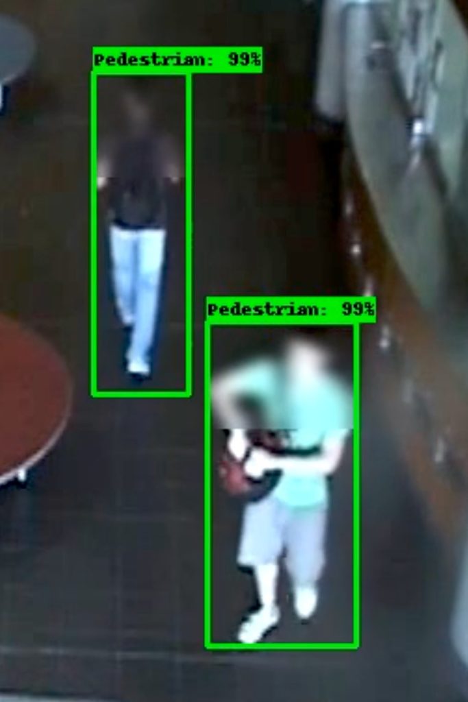
For instance, imagine you want to measure the distance between two people in a CCTV video frame for automatic social distancing detection. Even if you can detect the people in the video frame, determining their real-world distance using only pixel coordinates can be difficult. The distance between the people may appear smaller in the image than it actually is in the real world due to the lack of depth information. Camera calibration using homography estimation is a common technique to accurately map pixel coordinates to their corresponding real-world coordinates, making it possible to measure distances with confidence.
In this article, we’ll explore the challenges of measuring real-world distances using pixel coordinates and how homography estimation can help us overcome them. We’ll use the example of measuring the distance between people in a CCTV video, but the concepts we’ll cover apply to a wide range of applications (you can see some of the use cases in the following). By the end of this article, you’ll have a clear understanding of how camera calibration using homography estimation works and how it can help you take accurate measurements in your own projects.
💡 Camera Calibration Business Use Cases:
1- Security Companies could greatly benefit from automatic camera calibration for their surveillance systems. By improving the accuracy and reliability of their cameras, they could provide better identification and tracking of individuals or vehicles, In the presence of occlusion and across multiple cameras, leading to more effective prevention and response to security threats.
2- Retail stores could use automatic camera calibration to improve the customer experience and increase sales. By monitoring customer behavior, the system could identify areas of the store that are frequently congested or ignored and suggest changes to the store layout or product placement. This could lead to more efficient use of space and a better customer shopping experience, ultimately resulting in increased sales. Additionally, the system could be used to monitor for shoplifting or other security issues, further enhancing the overall security of the store.
3- Transportation Companies, such as airlines or shipping companies, could use automatic camera calibration to monitor cargo or baggage handling processes. By analyzing the movement of goods and personnel, the system could identify areas for process improvement and reduce the risk of damage or loss of goods. This could ultimately save the company money and improve customer satisfaction. Additionally, the system could be used to monitor for security threats, such as tampering with luggage or cargo.
4- Manufacturing Companies could use automatic camera calibration to monitor production processes and improve worker safety and productivity. The system could suggest changes to the manufacturing process or equipment placement by analyzing worker movements and identifying potential hazards or inefficiencies. This could lead to a safer and more efficient workplace, ultimately resulting in increased productivity and cost savings for the company.
5- Smart cities: Municipalities could use automatic camera calibration to optimize their transportation network and reduce congestion. By monitoring traffic flow and adjusting traffic signal timing accordingly, the system could improve the overall efficiency of the city’s transportation network. This could lead to reduced commute times, lower transportation costs for residents, and decreased traffic-related pollution. Additionally, the system could be used to monitor traffic accidents or other emergencies, improving the city’s overall safety.
From 3D Scene to 2D Image and Vice Versa
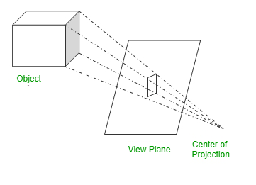
Cameras use perspective projection to map the world coordinates in 3D scenes into pixel coordinates in 2D images. Figure 2 illustrates an example of how cameras project the object of interest into a 2D plane using perspective projection.
We are interested in doing the exact opposite of what cameras do; to find a mapping from pixel coordinates of a point in an image to world coordinates of that point in the actual 3D scene.
In the social distancing application example that we mentioned earlier, if we find the pedestrians’ world coordinates, calculating the world distance between the people becomes trivial. To achieve the world coordinates, we need an approach to map the 2D coordinates on the image to 3D coordinates in the real-world scene, exactly in the opposite way of what cameras do.
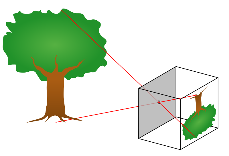
Pinhole Camera Model
Let us quickly explain the mathematics behind projecting a point from the 3D scene onto the 2D image. We will assume that we are working with an ideal pinhole camera with an aperture described as a point (see Figure 3).
The relationship between the world coordinates and the image coordinates can be expressed using the following formula:
(1)

On the left-hand side, we see the scale factor s and a vector representing the image coordinates. Note that we can always factorize this vector by s such that the third element becomes equal to 1. We calculate s,u,v based on the calculations on the right-hand side to map 3D world coordinates to 2D image coordinates.
On the right-hand side, we see two matrices, I,E ,and a vector K. The vector contains the world coordinates (X,Y,Z) of the point that we are trying to map to the 2D space with the fourth element set equal to 1.
The relationship between the world coordinates and the image coordinates depends on both the intrinsic and extrinsic characteristics of the camera. Therefore, two matrices I and E are introduced into the formula to capture these characteristics. Let us have a closer look at the parameters included in the intrinsic and extrinsic matrices:
Intrinsic Matrix
The intrinsic matrix I describes the camera’s internal specifications, such as the focal length and the principal point.
fx , fy : camera’s focal length (meters/pixels). Two parameters are introduced to describe cameras with rectangular pixels. If your camera uses square pixels, set fx = fy.
Cx , Cy : principal point or image center. The coordinates of the point at the intersection of the optical axis and the image plane.
Extrinsic Matrix
The extrinsic matrix E
rij : camera’s rotation matrix that describes the camera’s rotation angle in the installed environment.
ti : the camera’s offset from the origin of the world coordinate system.
Once you measure the mentioned parameters, you can plug them into the formula and do a simple matrix multiplication to obtain image coordinates.
Besides direct methods of measuring the camera’s intrinsic and extrinsic parameters, some alternative approaches can be used to estimate these parameters, such as Zhang’s method and Tsai’s algorithm. We encourage you to investigate these papers (1, 2) to learn more about these approaches.
The pinhole camera model maps the 3D world coordinates to 2D image coordinates by parameterizing the intrinsic and extrinsic characteristics of the camera. If we want to do the opposite and find the 3D world coordinates from the 2D image coordinates, we should calculate the inverse of matrices I and E and multiply the image coordinates vector by I-1 and E-1 to obtain values of the world coordinates. These calculations can be described using the following formula:
(2)

You can now plug image coordinates into this formula and obtain the corresponding world coordinates by doing simple matrix multiplications.
Don’t need that much information? Here’s the easier way.
The previous approach maps every point in the image coordinates to the corresponding point in the real-world’s coordinate system. However, in some applications, we do not need that much information to reach our final goal.
Let us picture the example of calculating the distances between the people again. If we want to measure the distances between the pedestrians using images (or videos) taken with a camera, do we need to map every point in the image to its corresponding coordinates in the world scene?
We know that the pedestrians are walking on the same plane, which is the ground. If we represent each pedestrian with a point on the ground plane and find the world distance between these points, the problem would be solved because these points are all on the same plane. Thus, we only need to calculate the world coordinates of the points on the ground plane for each pedestrian in order to find the pairwise distances between them.
In other words, we want to map the points that lie on one plane from the image coordinates to the world coordinates. Therefore, we will be using 2D vectors to represent both image coordinates and world coordinates that reside on the same plane. In Figure 4, for example, mapping the points that reside on the blue plane is sufficient to calculate the distance between the people who pass the corridor.
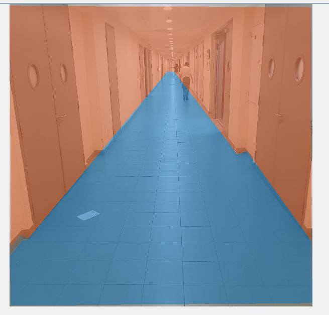
In this example, the problem is reduced to determining the world coordinates of the points residing in a two-dimensional plane instead of mapping the whole space. In such cases, we can apply a more straightforward method, called Homography Estimation, to find the world coordinates of points that lie on a plane (rather than the whole space) using fewer parameters.
Homography Estimation
In this approach, we use a matrix called the homography matrix to map the points residing on a plane from world coordinates to the corresponding image coordinates. Note that all the points that we are mapping are coplanar; therefore, we can represent the world coordinates with 2D vectors. The homography matrix H is a 3*3 matrix that contains the parameters h11, h12, h13, h21, … , h33. If we manage to figure out the values of h11 through h33 somehow, we can use the following formula to map the world coordinates to image coordinates:
(3)

In this formula, (x2, y2, z2) is a normalized vector with z2 = 1, and (x2, y2) is the coordinates of a point P within the image. Similarly, (x1, y1, z1) is a normalized vector with z1 = 1, and (x1, y1) describes the coordinates of P in the world coordinate system. By substituting the values of h11, … , h33. in the homography matrix H, we can calculate the image coordinates for each given point expressed in world coordinates.
If we want to do the mapping in the opposite direction, i.e., from the image coordinates to the world coordinates, we need to calculate the inverse of the homography matrix to get H-1 and multiply the image coordinates vector by H-1 to obtain the corresponding world coordinates. The following formula shows how we can find the world coordinates based on the image coordinates:
(4)

But how can we compute h11, … , h33 ?
Suppose that we have the world coordinates of four points (p1, p2, p3, p4) with their corresponding mapping (p'1, p'2, p'3, p'4) in the image coordinate system, where pi = (xi , yi) and p'i = (x'i , y'i) . Using these pairs of points, we can write a linear equation with eight equations and eight unknowns that describe h11, … , h32, and normalize the last parameter by considering h33=1.
To solve this system of linear equations, we rearrange the equations to gather all the variables on one side and form a PH = 0 equation as follows:
(5)

We can now use linear algebra algorithms, such as SVD, to solve this system for H. Having calculated H, we can find the image coordinates from world coordinates using formula 3. Finding world coordinates from image coordinates is also possible by plugging in H-1
All of the mathematics we explained above are implemented in a function in the OpenCV library. You can use this function to estimate the homography matrix in a single line of code. Let us explain how this method works.
Homography Estimation in a single line of code
To restate the problem, you have installed and fixed your camera somewhere, and you want to obtain the world coordinates (or distances) using a single image captured by your camera.
To do so, first, mark the four corners of an imaginary square (a 1m x 1m square is recommended for ease of calculations) on the ground and choose one of these points as the origin of the world coordinate system. Then, measure the X,Y coordinates of these four points according to the origin you just set. We call these numbers the source points.
Then, without changing the camera position or the heading angle, calculate the coordinates of the four points from the previous step, but this time in image coordinates. Let us call these coordinates the destination points.
We are trying to estimate the homography matrix H by finding a mapping between the source points and the destination points. Luckily, the OpenCV library has a function that does the calculations for us. The findHomography function takes in two sets of numbers, the source points and the destination points, and estimates the homography matrix based on the corresponding coordinates of these two sets of numbers. We can use this function to calculate H in a single line of code as follows:
h, status = cv2.findHomography(pts_src, pts_dst)
You can refer to the OpenCV documentation to learn more about this function. Figure 5 illustrates how this function works in practice. The four blue dots are the reference points to calculate H. The green dots computed using the homography matrix show the ground plane. The key point is that each two consecutive green dots has the same distance in the world coordinates, and the closer the points are to the camera, the more distant they are.
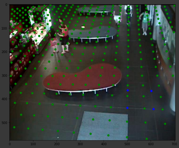
H, and the green dots show the ground plane.Camera Calibration using Homography Estimation; a Use Case
To see how this camera calibration method works in practice, we implemented this method in our open-source Smart Social Distancing application. This application calculates the world distances between people in an input video to measure how well social distancing is being practiced. You can learn more about this application here.
The Smart Social Distancing application implements three methods to calculate the world distance between the people; 1- the calibration-less method comparing bounding box center points, 2- the calibration-less method comparing bounding box corners, and 3- the camera calibration method using homography estimation. The calibration-less methods are explained in this article in detail.
The user can select the method they want to use by specifying the method name in the application configuration file. If the camera calibration method is selected, the user should also specify the path to a .txtH-1) in the config file. In future updates, we will implement an interface for the user to mark the corners of a square that is 1 meter long on each side. The user can leave the rest of the calculations to the app.
Our pedestrian detection model outputs a rectangular bounding box around each detected pedestrian. For each bounding box, the bottom side of the rectangle lies on the ground plane. Thus, to measure the distance between the pedestrians, we take the middle point of each rectangle’s bottom side to estimate the intersection of the person with the ground and find its world coordinates (by multiplying H-1 with the pixel coordinates vector). Finally, we calculate and report the pairwise Euclidean distance as the distance between the detected pedestrians.
Note that since the reference square that we marked on the ground was a 1m x 1m square, the calculated distances preserve the real-world scale and are in meters. Therefore, no further calculation, such as rescaling or normalization, is needed.
Conclusion
Cameras project 3D scenes onto 2D images. The pinhole camera model shows the relationship between the world coordinates and image coordinates using the intrinsic and extrinsic matrices that capture different characteristics of the camera.
If we want to find the relationship between the image coordinates and world coordinates of points that reside on the same plane (coplanar points), we can use homography estimation. The homography matrix can be estimated using two corresponding sets of points, one in world coordinates and the other in image coordinates. The OpenCV library provides a useful function that takes in the two sets of numbers as input and returns the homography matrix as output.
We have implemented the homography estimation algorithm for camera calibration in our Smart Social Distancing application. In future updates, we will add an interface for camera calibration in our app.
Questions & Answers
Here are some burning questions about camera calibration that you can answer by reading this article.
1- What is camera calibration, and why is it important for computer vision applications?
Camera calibration is the process of estimating a camera’s intrinsic and extrinsic parameters. Intrinsic parameters include the focal length, image sensor format, and optical center of the camera, while extrinsic parameters include the camera’s position and orientation in 3D space. Camera calibration is an essential step in many computer vision applications and is necessary for achieving accurate and reliable results in many detections, tracking, and many other computer vision tasks.
2- What is a Pinhole camera model?
The pinhole camera model is a simplified representation of how light travels through a camera to create an image. It assumes that light enters the camera through a single point, forming an inverted image on the opposite side. The model can be extended to include the intrinsic and extrinsic matrices used for camera calibration and other computer vision tasks. The intrinsic matrix contains information about the internal parameters of the camera, such as the focal length and lens distortion. In contrast, the extrinsic matrix contains information about the camera’s position and orientation in 3D space. Combining the pinhole camera model with the intrinsic and extrinsic matrices makes it possible to accurately model the relationship between points in the 3D world and their projections onto the camera’s image plane, enabling accurate calibration and reliable computer vision results.
3- What is homography estimation, and how is it used for camera calibration?
The article explains the concept of homography estimation and how it is used for camera calibration, specifically in the context of planar calibration targets.
4- What mathematical model is used for camera calibration using homography estimation?
The article provides a detailed explanation of the mathematical model used for camera calibration using homography estimation, including the homography matrix and the camera projection matrix.
5- How can camera calibration using homography estimation be implemented in practice?
The article provides a step-by-step guide for implementing camera calibration using homography estimation, including capturing calibration images, extracting calibration points, and estimating the homography matrix.
Further Readings
1- The Geometry of Image Formation
This tutorial explains the math behind projecting a 3D point onto a camera’s image plane, using Extrinsic and Intrinsic matrices. Suitable for beginners with matrix multiplication knowledge.
2- Camera Parameters
This article delves into the camera geometry, focusing on the important parameters within the camera model. The parameters covered are crucial for various computer vision tasks, and the article emphasizes the need to compute and calibrate them using specific methods.
3- Homography Estimation
This is a short handbook by David Kriegman exploring the Homography Estimation parameters and formulas. It discusses formulas in four sections: From 3D to 2D coordinates, homography estimation, homogeneous linear least squares, and homogeneous linear least squares alternate derivation.
Leave us a comment
Comments
Get Started
Have a question? Send us a message and we will respond as soon as possible.
I have learn several just right stuff here. Definitely value bookmarking for revisiting. I surprise how much attempt you place to make this kind of wonderful informative site.